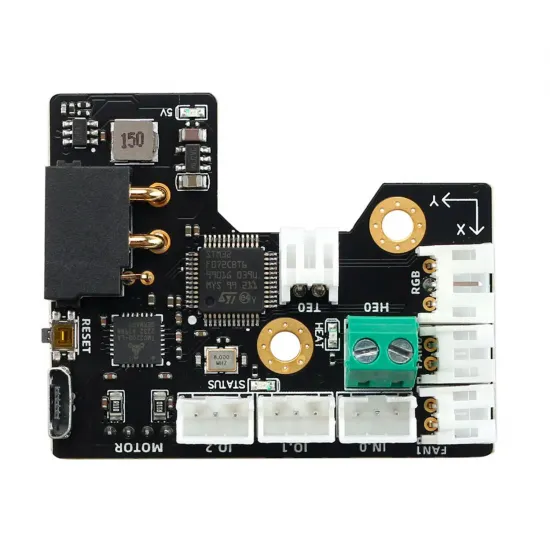


- Stock: Out of Stock
- Model: SBCAN-Fysetc

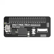
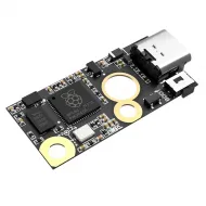
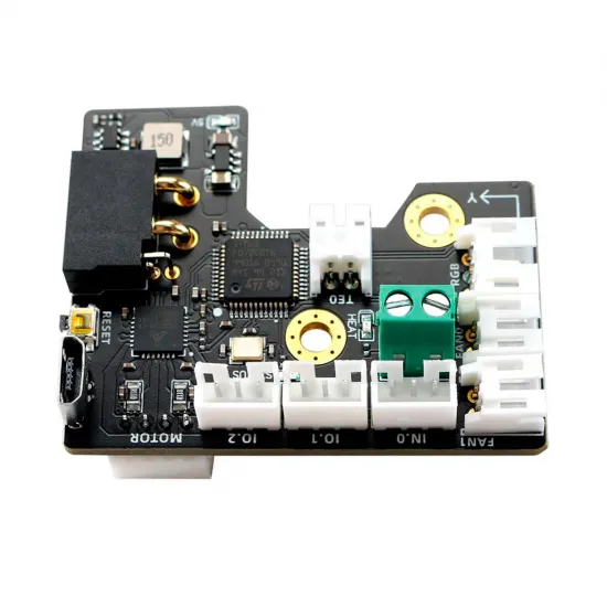
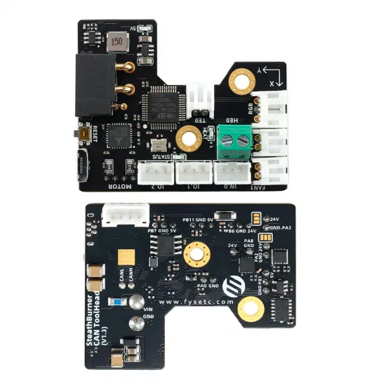
The FYSETC SB CAN ToolHead V1.3 brings the StealthBurner printhead electronics together on one board. It controls the extruder motor through an integrated TMC2209 driver, the heater and temperature sensor, two fans, RGB lighting, and inputs for a probe or endstop. An onboard ADXL345 supports Klipper resonance measurements. CAN communication lets you organise the toolhead around a combined power-and-data loom, while the printer's main board continues to control the motion axes.
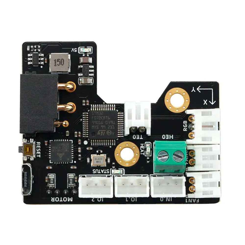
What is built in
- STM32F072 microcontroller and CAN transceiver. It operates as an additional Klipper MCU, not as the host computer or a replacement for the printer's main board.
- Integrated TMC2209 driver for one extruder motor, with UART communication. Set motor current and movement parameters for the actual extruder.
- Integrated ADXL345 for resonance measurements. Sensor orientation and measurement location depend on installation.
- Four-way power/CAN input, heater and temperature connections, two fan outputs, RGB and three signal interfaces.
Connections and important limits
| Connection | Purpose and checks |
|---|---|
| Power and CAN | 24 V input, GND, CAN_H and CAN_L on a four-way connector. Check each conductor's position and provide a correctly configured CAN interface on the host or another board. |
| MOTOR | Four-wire extruder motor connector driven by the integrated TMC2209. Identify the motor's coil pairs before connecting. |
| HE0 / TE0 | PWM heater output and analogue temperature input. FYSETC states up to 4 A for HE0 and recommends a heater of no more than 60 W. Configure the thermistor curve for the installed sensor. |
| FAN0 / FAN1 | Two PWM outputs rated up to 0.5 A each. Fan supply can be selected between VIN and 5 V; check the board selection and each fan's rated voltage before connection. |
| IN.0 / IO.1 / IO.2 | IN.0 has level adaptation for a sensor signal supplied from 24 V. IO.1 and IO.2 provide 5 V for peripherals; do not apply 24 V directly to them. Check the probe type, signal logic and wiring separately. |
| RGB | Signal output for 5 V addressable LEDs, with a 1 A limit stated by FYSETC. LED count and colour order depend on the installed assembly. |
| USB | Port for firmware programming and maintenance. Normal toolhead operation uses CAN. |
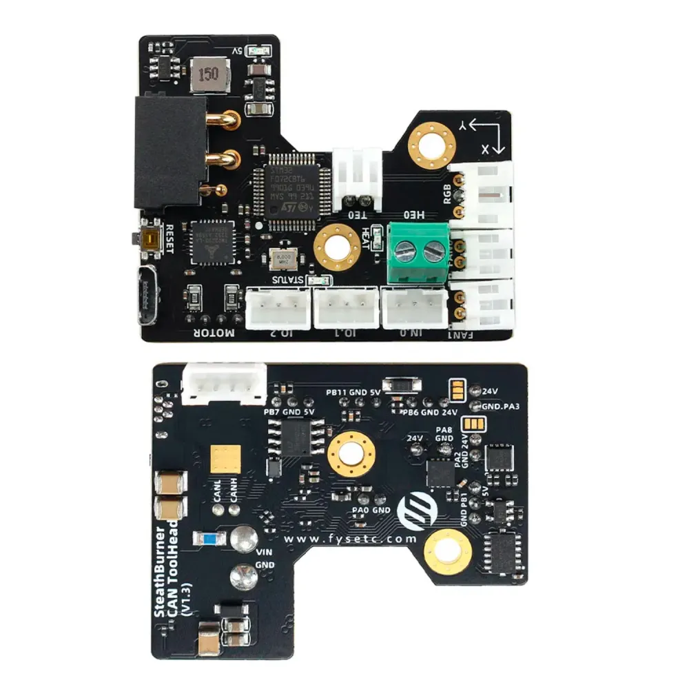
StealthBurner mounting and printer compatibility
This board was designed for a StealthBurner toolhead with a Clockwork 2 extruder and suitable mounting parts. FYSETC publishes a PCB spacer and adjusted printed parts. A StealthBurner or Voron 2.4/Trident name alone therefore does not guarantee a direct fit: compare the bracket, fasteners, connector clearance, motor, hotend, probe and cable routing. For that project, see our StealthBurner and Clockwork 2 printed-parts kit, and check any adaptation needed for this board before assembly.
CAN reduces the number of separate signal wires through the printhead, but it does not replace the 24 V supply, moving-loom protection or the system's CAN interface. Nor does it add extra axes or bed outputs to the main controller.
Klipper integration
- Prepare the CAN bus. Use a compatible CAN adapter or a board configured as a USB-CAN bridge. Connect power, ground, CAN_H and CAN_L according to the pinout and check termination. Klipper calls for two 120 Ω resistors, one at each bus end; with power off, a reading near 60 Ω between CAN_H and CAN_L is a useful overall check.
- Build firmware for this MCU. Select STM32F072 and CAN communication when compiling Klipper. CAN speed, bootloader offset and flashing method must match your actual network and firmware; do not copy settings from another board.
- Identify your own board. After flashing and connecting CAN, obtain its unique identifier with
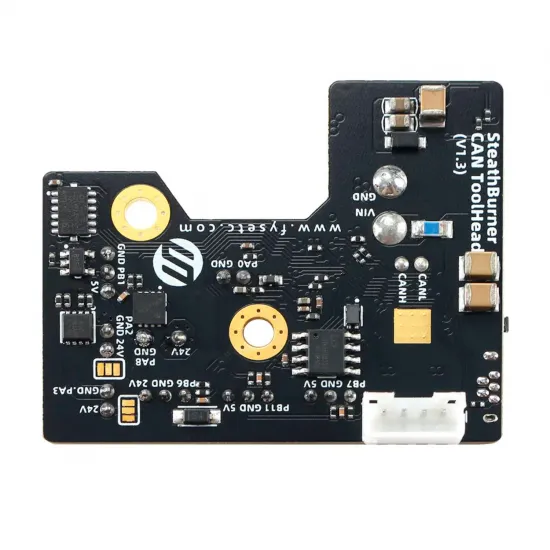
~/klippy-env/bin/python ~/klipper/scripts/canbus_query.py can0. Add an[mcu sb_can_th]section with that unit'scanbus_uuid. An identifier from an online example is not shared by all boards. - Configure peripherals. FYSETC documents motor STEP/DIR/EN on PA7/PA5/PB4, TMC2209 UART on PA10/PA9, heater PA8, sensor PA0, FAN0/FAN1 PA2/PA3, RGB PB1 and IN.0 PB6. The onboard ADXL345 uses PB12/PB13/PB15/PB14 for CS/CLK/MOSI/MISO. Cross-check these against the physical revision, schematic and wiring before powering a load.
- Calibrate the printer. Set the real thermistor type, motor current, extruder ratio, thermal limits, PID, probe and accelerometer orientation for your hardware. FYSETC's example file contains machine-specific values and is not a universal ready-to-use configuration.
See Klipper's CAN guide and the FYSETC technical repository for the pinout, mounting files and reference configuration.
Before switching on
Do not connect or disconnect the 24 V supply while it is live. FYSETC warns that hot-plugging can damage the board's fuse. Check polarity, insulation, fan voltage, CAN_H/CAN_L assignment, termination and cable strain relief. V1.3 has a RESET button for FYSETC's flashing procedure; do not apply the V1.1 power-up sequence. Before printing, verify temperature readings, extruder rotation, fans and probe, and keep Klipper's thermal protections enabled.
Is it right for you?
Yes, if you are building a StealthBurner with suitable mounting parts, use Klipper and want motor, heating, fans, RGB and resonance measurement on a CAN toolhead. No, if you need a complete main board, installation without firmware and wiring work, or a guaranteed mechanical drop-in for every Voron printhead.
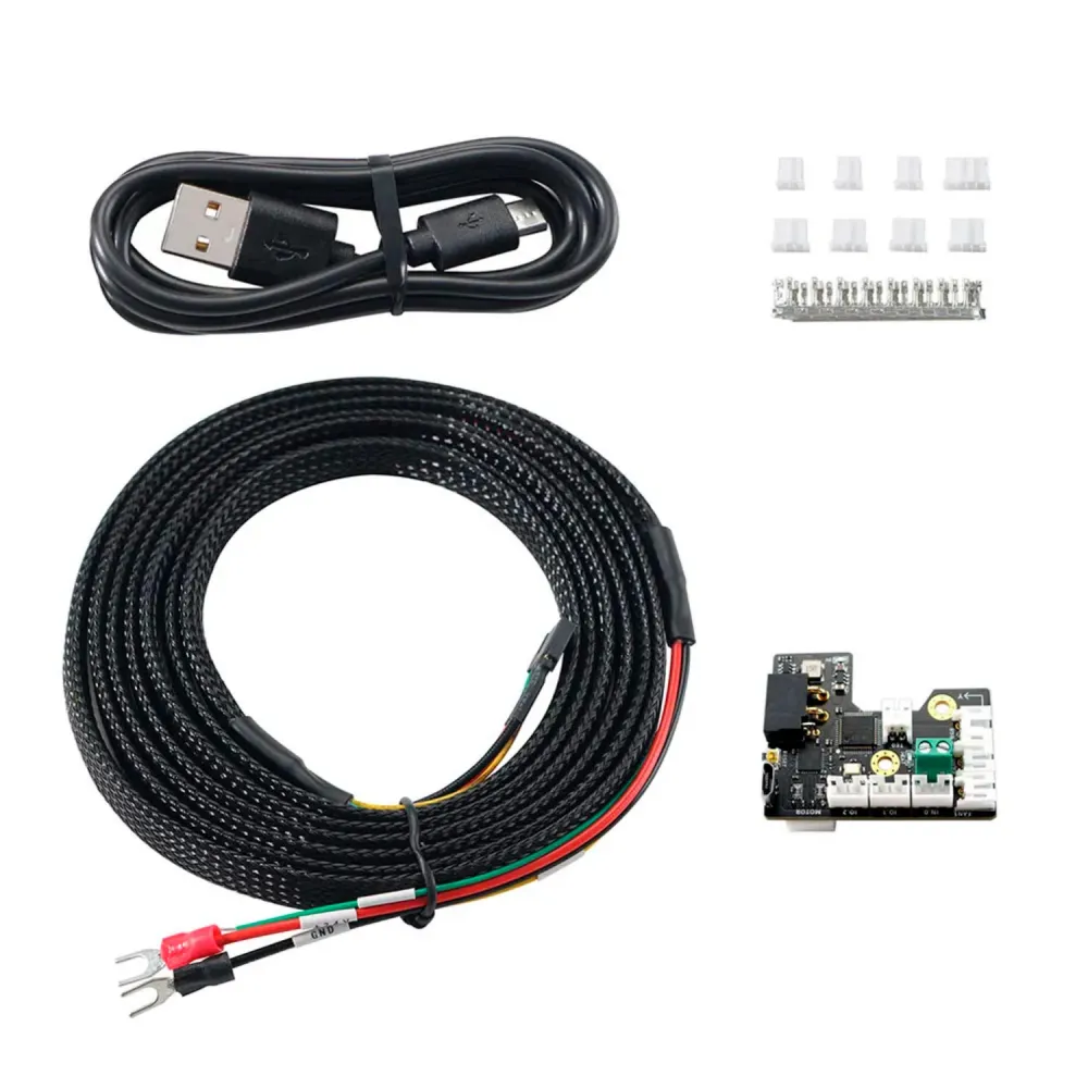
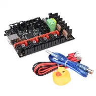
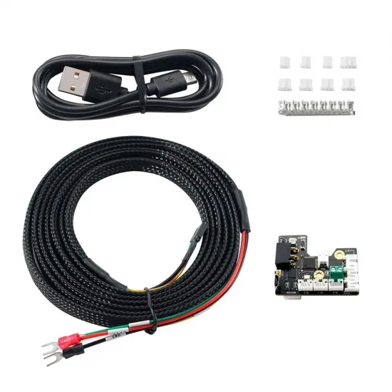
In the kit: FYSETC SB CAN ToolHead V1.3 board, 2.5 m four-core power/CAN cable, USB cable, and connector housings/terminals shown with the product. Printed parts, host and system CAN interface are selected for the specific printer.