

- Stock: 1
- Model: S6-fysetc

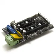
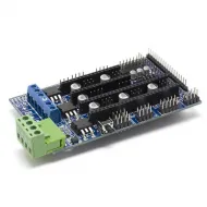
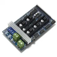
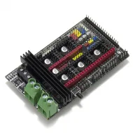
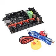
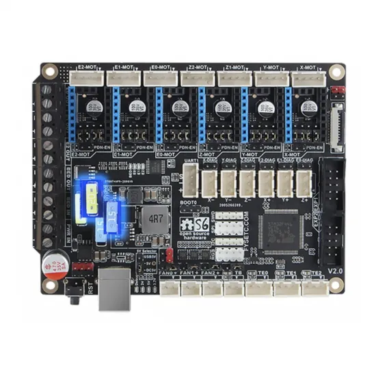
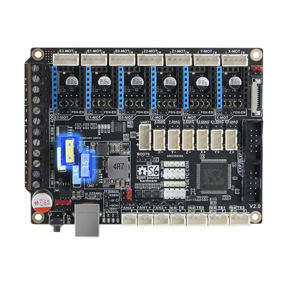
The FYSETC S6 V2.1 XH is a 32-bit controller board for 3D printers and custom machines requiring multiple motors, heaters, fans and peripherals. It is built around a 180 MHz STM32F446VET6 and provides six replaceable StepStick driver sockets.
This product is exclusively the XH connector version. It is a flexible controller for Marlin or Klipper projects, but it is not a universal drop-in replacement: firmware, drivers, wiring, connectors, voltages and configuration must match the exact machine.
Main features
| Feature | Specification |
|---|---|
| Manufacturer and revision | FYSETC S6 V2.1, XH version |
| Microcontroller | 32-bit STM32F446VET6, up to 180 MHz |
| Power | 12 or 24 V DC; 28 V is the published maximum, not the recommended operating voltage |
| Drivers | 6 replaceable StepStick sockets: X, Y, Z, E0, E1 and E2 |
| Motors | 7 connectors; Z1 and Z2 share the Z driver and are wired in series |
| Heaters | 1 bed and 3 hotend outputs |
| Temperature | 4 inputs: bed and three hotends |
| Fans | 3 PWM outputs |
| Expansion | EXP1/EXP2, display, SD, UART, SPI, I²C, servo/probe, endstops and RGB |
| Dimensions | 117 × 87 mm |
Six replaceable drivers and seven motor connectors
The six sockets let you choose a suitable driver for each axis and replace it as the machine evolves. The board supports STEP/DIR operation and, with compatible modules and correctly installed jumpers, UART or SPI communication.
The Z output provides two connectors, Z1-MOT and Z2-MOT, powered by one driver and wired in series. This can run two Z motors that must move together, but it does not provide independent control or dual-driver gantry levelling.
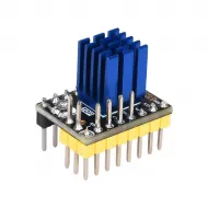
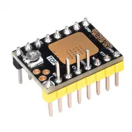
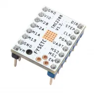
For quiet operation with UART configuration, it can be paired with the FYSETC S2209 V4.0 TMC2209 driver. Compatibility requires checking orientation, pinout, voltage, current, jumpers and cooling; a StepStick footprint alone does not prove safe compatibility.
UART, SPI and sensorless homing
- UART: on S6 V2.x it is enabled through each socket's PDN-EN/JP1 jumper without flying UART wires.
- SPI: requires the four jumpers shown by FYSETC and a driver prepared for SPI.
- Standalone STEP/DIR: microstep selection depends on the physical jumpers and installed module.
- Sensorless homing: requires a compatible driver, its DIAG jumper and correct firmware configuration. Installing a TMC alone does not enable the feature.
Never insert or remove drivers, motors or jumpers while the board is powered or connected over USB. Check module orientation carefully, as reversing a driver can damage both parts.
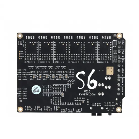
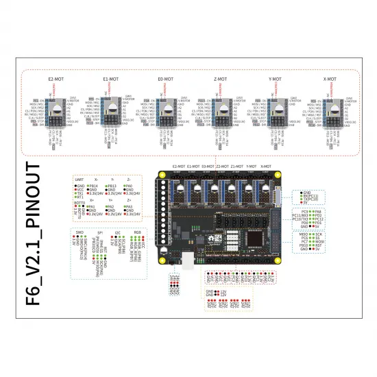
Main V2.x pin map
| Channel | STEP | DIR | ENABLE | UART TX |
|---|---|---|---|---|
| X | PE11 | PE10 | PE9 | PE8 |
| Y | PD8 | PB12 | PD9 | PC4 |
| Z | PD14 | PD13 | PD15 | PD12 |
| E0 | PD5 | PD6 | PD4 | PA15 |
| E1 | PE6 | PC13 | PE5 | PC5 |
| E2 | PE2 | PE4 | PE3 | PE0 |
| Group | Documented pins | Notes |
|---|---|---|
| Temperature | T0 PC0 · T1 PC1 · T2 PC2 · TB PC3 | Configure the exact curve of the connected sensor |
| Heaters | HE0 PB3 · HE1 PB4 · HE2 PB15 · BED PC8 | Check load power, wiring and thermal protection |
| Fans | FAN0 PB0 · FAN1 PB1 · FAN2 PB2 | Check voltage and polarity before connection |
| Minimum endstops | X- PB14 · Y- PB13 · Z- PA0 | Logic and pull-ups depend on the sensor |
| Maximum endstops | X+ PA1 · Y+ PA2 · Z+ PA3 | PA3 is also used as SERVO0 |
| Driver SPI | MOSI PE14 · MISO PE13 · SCK PE12 | Each socket additionally uses its own CS line |
Power, fuses and selectors
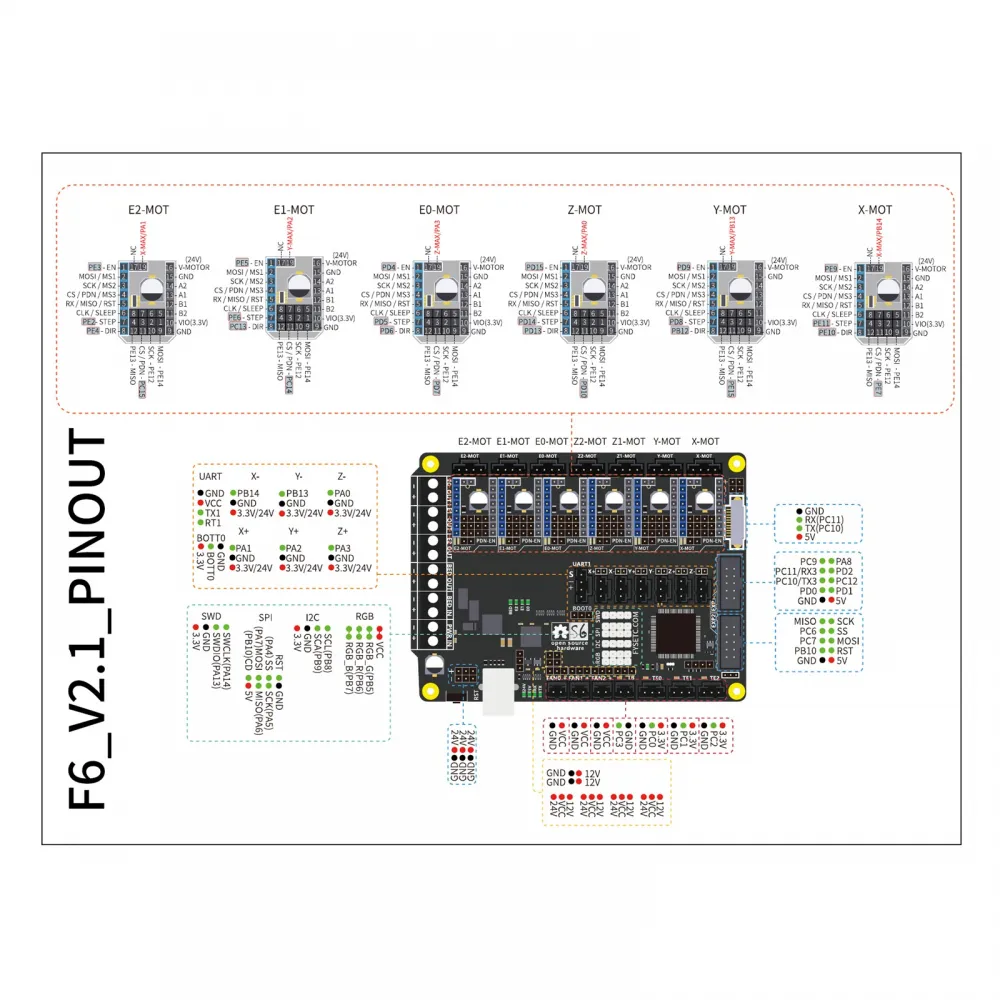
The S6 provides separately fused main and heated-bed power inputs. Size the supply, fuses, conductors, ferrules, connectors and power stage for the actual installation current. A fuse rating alone is not the continuous-current rating of an output.
FYSETC provides physical voltage selectors for certain sensor and peripheral connectors. Firmware cannot correct a jumper placed on the wrong voltage. Identify signal, positive and GND from the diagram and never infer a wire's function from colour alone.
DC5V position. Its documentation warns that with the jumper on USB5V, 24 V power applied and USB disconnected, heater outputs may activate. Check this selector before the first power-up.The regulated output labelled 12 V needs input headroom: FYSETC specifies an input above 15 V and recommends more than 18 V for satisfactory 12 V output. When powering the board from 12 V, do not assume that this rail provides regulated 12 V.
Temperature sensors and thermocouples
T0, T1, T2 and TB are analogue inputs. Firmware must declare the exact sensor model or curve: knowing only that a thermistor is nominally 100 kΩ does not identify its thermal response.
The board supports integration of an AD597 thermocouple module, but this requires the modifications and connections documented by FYSETC. It is not a direct universal thermocouple input. Before enabling any heater, all temperature readings must be physically plausible and close to ambient.
Displays and expansion
EXP1 and EXP2 can support compatible displays when power, signals, orientation and configuration match. The board may be paired with the FYSETC Mini 12864 V2.1 RGB display, but similar connectors do not guarantee a direct connection: check both revisions' pinouts, cable orientation and RST/KILL function before applying power.
Marlin setup
Marlin uses the following board definition for the S6 V2.x family, including the commercial V2.1 revision:
#define MOTHERBOARD BOARD_FYSETC_S6_V2_0There is no separate V2.1 board definition. You must then select the installed drivers and configure their currents, microsteps, thermal sensors, heaters, fans, probe, endstops, dimensions and actual machine kinematics.
Boards using the current 32 KiB bootloader use the STM32F446VE_fysetc_32k_bootloader environment. STM32F446VE_fysetc targets the older 64 KiB bootloader. FYSETC changed the distributed bootloader in 2021; although a V2.1 will normally be newer, verify the installed bootloader before building or flashing. An incorrect offset can prevent the board from booting.
Klipper setup
FYSETC documents the following Klipper build basis:
- STM32F446 microcontroller;
- 12 MHz crystal;
- bootloader offset matching the actual board: normally 32 KiB on current units, 64 KiB on older units, or no bootloader when deliberately installed that way.
Build printer.cfg from a current configuration for the exact machine and adapt MCU, motors, drivers, endstops, thermistors, heaters, fans and display. Never copy USB identifiers, currents, PID values, travel limits or temperatures from a different printer.
Safe commissioning
- Disconnect both power supply and USB before working on wiring, drivers or jumpers.
- Confirm the S6 V2.x revision, XH version and every connector's orientation.
- Set UART, SPI, DIAG, microstep and peripheral-voltage jumpers.
- Check polarity, continuity, terminals, fuses and absence of short circuits.
- On first power-up, establish MCU communication without enabling high-power loads.
- Validate endstops and temperature readings while the machine is stationary and cold.
- Test each motor at low speed and each fan separately.
- Test heaters individually, under supervision and with thermal protection enabled.
- Calibrate directions, travel, extrusion, currents and PID before unattended printing.
It is for you if
- You need up to six replaceable drivers and several heater outputs.
- You are configuring a custom Marlin or Klipper printer.
- You can verify pinout, jumpers, XH connectors and firmware before commissioning.
It is not for you if
- You need a plug-and-play board for a commercial printer without adapting wiring or firmware.
- You need two independently controlled Z motors: Z1 and Z2 share one driver.
- You cannot verify the bootloader, peripheral voltages or each driver's configuration.
Contents
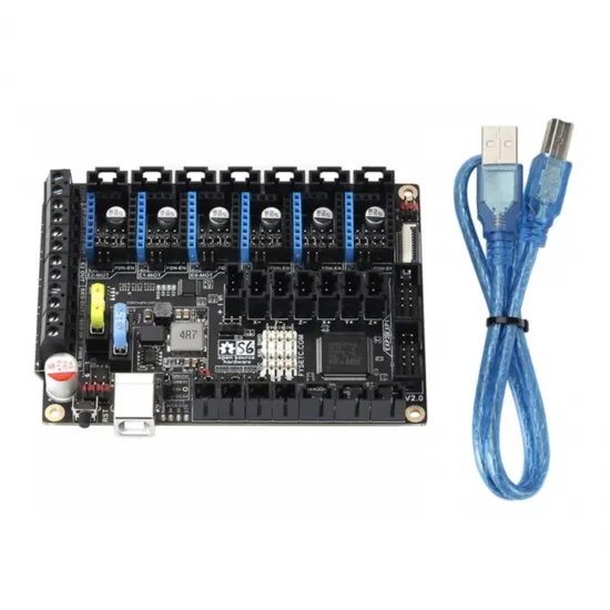
- 1 × FYSETC S6 V2.1 controller board, XH version.
See the official FYSETC S6 repository for pinout, schematics and firmware files. Always verify that the documentation matches the installed board revision.