

- Stock: In Stock
- Model: PrintedParts-ERCFv2
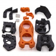
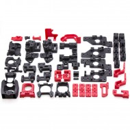
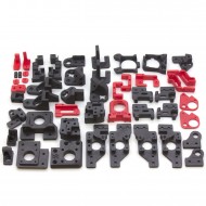
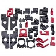
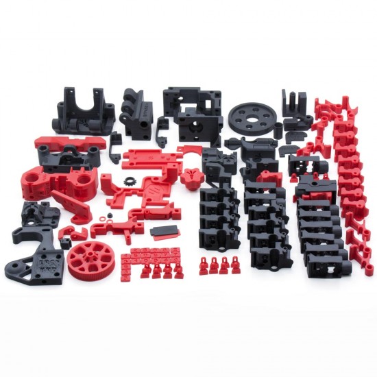
ABS printed-parts kit for building the core Enraged Rabbit Carrot Feeder v2 (ERCF v2), an expandable multi-material unit for Klipper-based 3D printers. ERCF selects one gate and feeds one filament at a time to a single print head, enabling automatic colour or material changes.
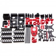
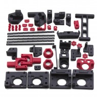
The parts are printed to order. Choose between 4 and 15 gates, the motor arm matching a NEMA 14 or NEMA 17 motor and the controller location, and the accent-part colour. Primary parts are printed in black.
What you are buying
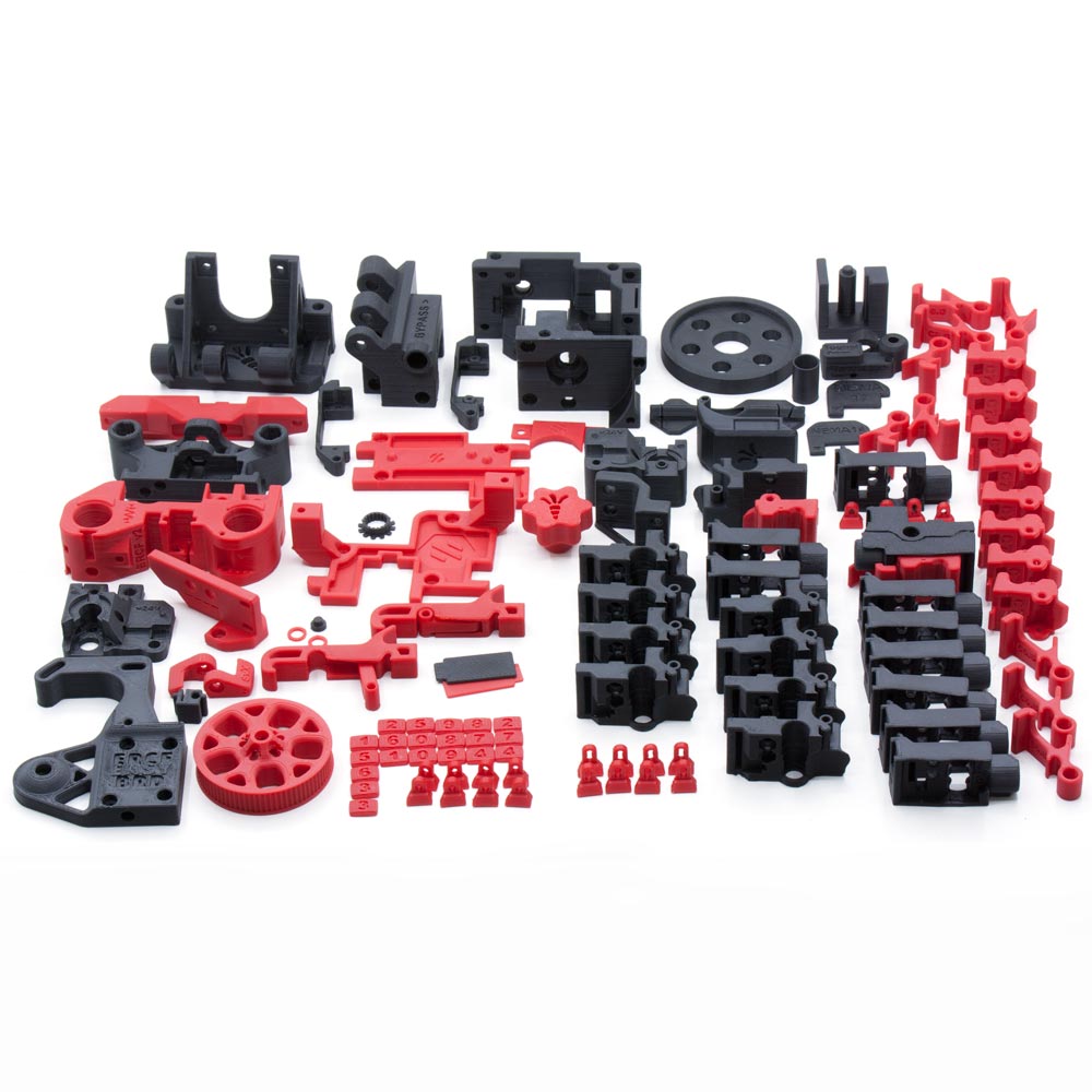
This product includes the ERCF v2 printed parts and the printed assembly tools listed below. It is not a complete ERCF: the extrusion, shafts, motors, servo, electronics, transmission components, bearings, sensors, fasteners, PTFE tube and the remaining official BOM hardware must be sourced separately.
The selected gate count changes both the number of printed filament blocks and the required extrusion, drive-shaft and selector-rod lengths. Check every option before ordering.
Options to select
| Option | Choices | How to choose |
|---|---|---|
| Gate count | 4 to 15 | It must match the number of filaments you want available and the Happy Hare configuration. |
| Motor Arm | NEMA 14, NEMA 14 EASYBRD, NEMA 17 or NEMA 17 EASYBRD | First choose the gear-axis motor size. The standard version is prepared for wiring to a remote MCU; the EASYBRD version is intended for a local MCU fitted next to ERCF. |
| Accent colour | Red, black, grey, white, yellow, orange, blue, silver or green | Applied to parts whose filenames begin with [a]_. Primary parts are black. |
About the EASYBRD option: it describes geometry intended for a local controller installed close to ERCF. The manual also discusses other dedicated MCUs such as BTT MMB, Mellow Fly ERCF BRD and FYSETC ERB. Check the board, connectors and wiring route used by your particular build.
Printed kit contents
The letter N represents the selected number of gates. One motor arm matching the selected option is supplied.
| Group | Included printed parts |
|---|---|
| Assembly tools | 80T_Cog_Guide, PTFE_Tool, Bearing_Install_Tool, Pulley_Tool_NEMA17, Pulley_Tool_NEMA14 and Slotted_Wheel_Push_Tool. |
| Gearbox | 2 × [a]_Bearing_Spacer; [a]_Gear_Box_Bottom_Panel; [a]_Gear_Box_Top_Panel; [a]_Knob; [a]_Logo_Plate; [a]_M4_80T_Wheel; 2 × [a]_Side_Latch; Gear_Box_Back; Gear_Box_Front; and the selected Motor_Arm. |
| Linear axis | [a]_Drag_Chain_Anchor_Bottom, [a]_Motor_Lock, Linear_Axis_Idler_Block and Linear_Axis_Selector_Motor_Support. |
| Filament blocks | N × [a]_Base_Trap_M3; N × [a]_Base_Trap_V-Shape; [a]_End_Bypass_Foot; N × [a]_Latch; N × [a]_Tophat; N × Base; End_Bypass; N × Filament_Path; and numbered identification plates for the selected gates. |
| Selector and encoder | [a]_Selector_Cart; MG90S and Savox servo arms; [o]_Encoder_Slotted_Wheel; Belt_Tensioner; Drag_Chain_Anchor; Encoder_Left; Encoder_Right; Selector_Door; Selector_Spring_Cap; and MG90S and Savox servo mounts. |
The encoder slotted wheel is printed in an opaque material, preferably black, because light passing through its vanes may cause incorrect optical readings.

Material and manufacturing criteria
The ERCF v2 project was designed and tested with ABS, so this kit is produced in ABS. Official documentation recommends a 0.2 mm layer height, four walls, five solid top and bottom layers and 40% infill. These are functional parts featuring press fits and plastic-on-plastic mechanisms, making dimensional consistency and print quality particularly important.
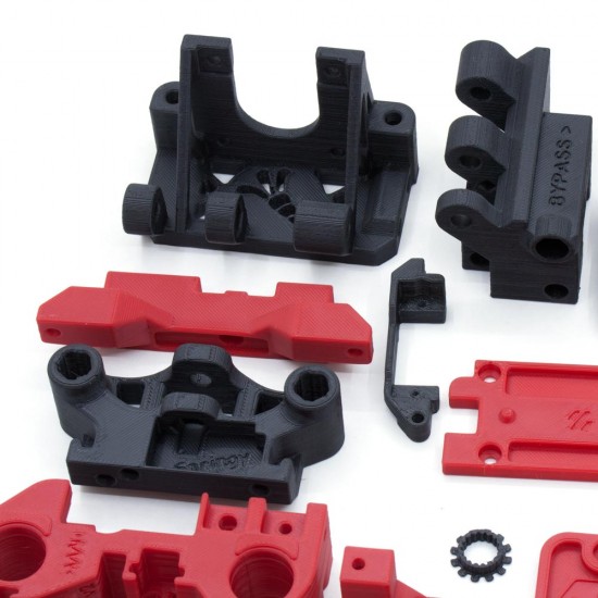
As with any FDM part, layer lines and minor process marks may be visible. Before assembly, remove the built-in supports identified by the manual, carefully clean only the required interfaces and confirm that moving joints operate without abnormal binding.
Extrusion and shaft lengths by gate count
The following nominal lengths are taken from the official assembly manual. They are useful when preparing the hardware, but should be checked against the current BOM and CAD before cutting.
| Gates | 2020 extrusion | Ø5 mm D shaft | 2 × Ø8 mm rods |
|---|---|---|---|
| 4 | 147 mm | 164 mm | 145 mm each |
| 5 | 170 mm | 187 mm | 168 mm each |
| 6 | 193 mm | 210 mm | 191 mm each |
| 7 | 216 mm | 233 mm | 214 mm each |
| 8 | 239 mm | 256 mm | 237 mm each |
| 9 | 262 mm | 279 mm | 260 mm each |
| 10 | 285 mm | 302 mm | 283 mm each |
| 11 | 308 mm | 325 mm | 306 mm each |
| 12 | 331 mm | 348 mm | 329 mm each |
| 13 | 354 mm | 371 mm | 352 mm each |
| 14 | 377 mm | 394 mm | 375 mm each |
| 15 | 400 mm | 417 mm | 398 mm each |
HTA3D stocks 1 m 2020 extrusion for cutting and cut-to-length Ø8 mm stainless smooth rod.
Hardware to be added
Always refer to the official BOM for the selected number of gates and options. The build uses, among other items:
- 2020 extrusion, a 5 mm D shaft and two 8 mm smooth rods.
- A NEMA 14 or NEMA 17 gear-axis motor and a compact NEMA 17 selector motor.
- A compatible MG90S or Savox positional servo. See our 180° MG90S micro servo.
- 20-tooth GT2 pulleys, a 188 mm closed-loop belt and an open selector belt. See the 20T GT2 pulley for a 5 mm shaft and 20T GT2 idler with a 5 mm bore.
- Bearings, filament-drive gears, ECAS fittings, magnets, springs, inserts and fasteners.
- Two LM8UU linear bearings or two Igus RJ4JP-01-08 bushings, depending on the selected solution.
- Controller board, drivers, wiring, endstop, encoder and any additional sensors.
- Guide tubing; 4 × 2 mm PTFE tube is available by the metre.
The M3 heat-set inserts and Ø6 × 3 mm neodymium magnets may be used in their corresponding locations, but check quantities and lengths against the BOM before ordering.
3D printer compatibility
ERCF v2 was primarily developed around Voron printers and direct-drive toolheads, but it can be adapted to other printers running Klipper. This does not make it a universal accessory or a drop-in upgrade for every printer.
Before starting, check:
- The printer can run Klipper and Happy Hare.
- There is sufficient room for ERCF, spools, buffer and tube paths.
- The toolhead can load and unload filament in a controlled manner.
- Enough drivers, inputs, outputs and power capacity are available for the motors, servo and sensors.
- The Bowden path has low friction and follows the filament's natural curvature.
- The slicer and macros can manage tool changes and purging.
A toolhead filament sensor is not strictly required, but the project recommends one because it provides a reference point close to the nozzle and improves loading, unloading and error-recovery reliability.
ERCF, ERCT and ERF are different subsystems
- ERCF: the main selector and filament-feeding unit. Its printed parts are covered by this product.
- ERCT or Cotton Tail: an optional passive buffer that manages filament unloaded during a tool change.
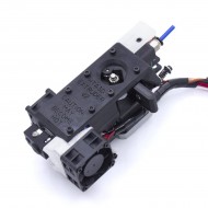
- ERF or Filametrix: an optional toolhead modification that cuts the filament tip to make the next load easier.
ERCT, ERF, printer-specific mounts, toolhead modifications and their printed parts are not included unless expressly agreed.
Klipper and Happy Hare setup
The recommended integration is Klipper + Happy Hare. No universal configuration is supplied because pins, currents, motor directions, sensors and limits depend on the selected board and hardware.
- Install and validate Klipper on the printer before adding the multi-material system.
- Install the current Happy Hare version using its interactive installer.
- Select ERCF, version 2.0, the actual gate count and the controller board used.
- Configure the MCU connection and verify pins before powering motors or the servo.
- Test the selector, gear drive, endstop, servo, encoder and additional sensors individually.
- Run selector, filament-drive, encoder, Bowden-length and toolhead calibrations.
- Configure the slicer and validate several manual tool changes before starting a long print.
Refer to the official ERCF v2 repository, the illustrated assembly manual and the current Happy Hare documentation.
This is for you if…
- You want to build an open and highly configurable multi-material system.
- You use Klipper and are prepared to spend time on assembly, wiring and calibration.
- You want functional ABS parts without printing the entire set yourself.
- You need between 4 and 15 gates and value an open, repairable and modifiable design.
This is not for you if…
- You need a complete, closed and plug-and-play device.
- Your printer cannot run Klipper or accept the required modifications.
- You do not want to complete the mechanical/electronic BOM and calibration process.
- You need guaranteed compatibility based solely on the printer's commercial model name.
Production and lead time
The parts are printed after purchase, and preparation time depends on the selected gate count, options and current print queue. As a guide, it may range from approximately 4 days to 2 weeks. Contact us before ordering if you need the current estimate.