

- Stock: 185
- Model: ZShaft-Voron
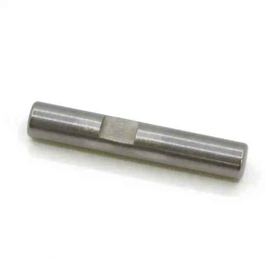
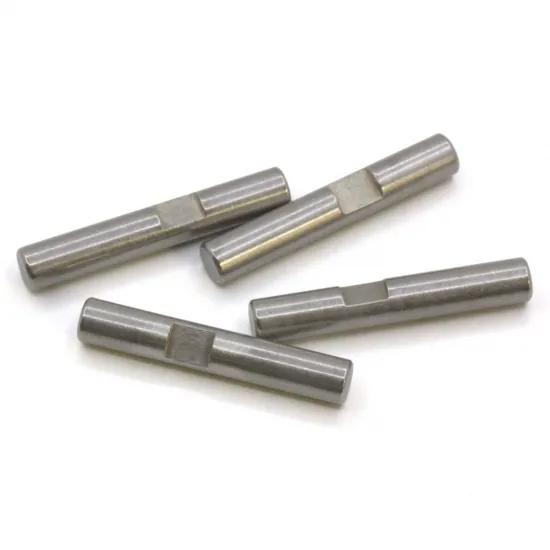
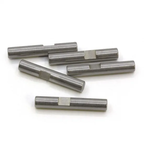
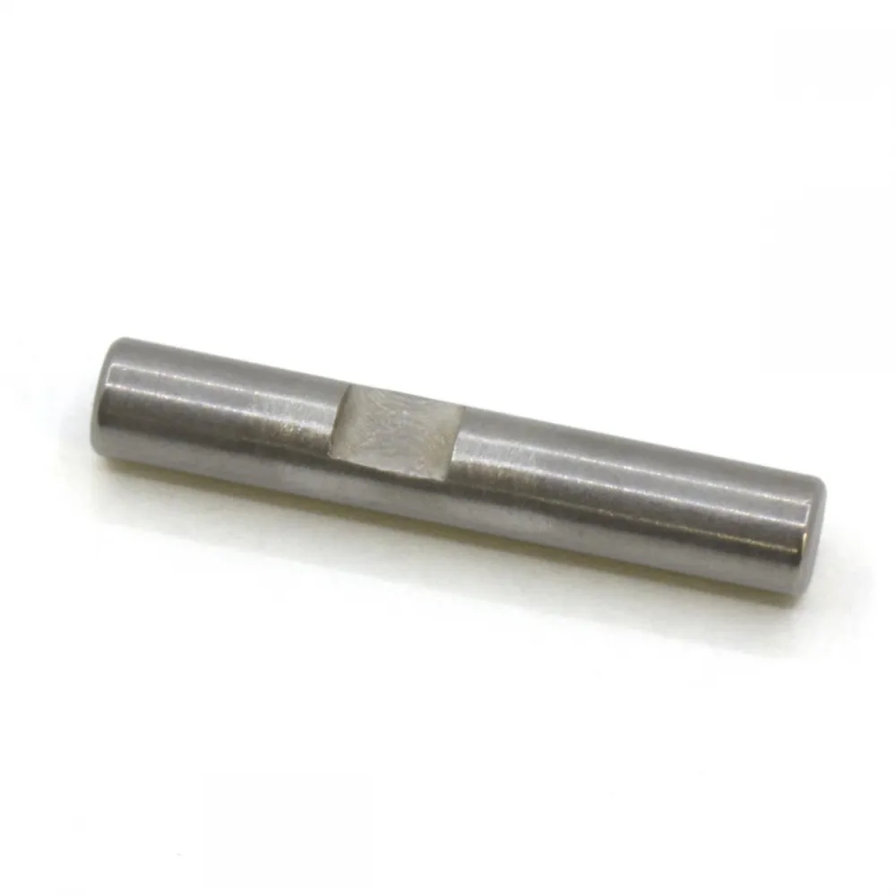
Machined 5 mm diameter and 30 mm long pin for the mechanical Z endstop used on Voron printers.
Its primary compatibility is with the Voron Trident. It may also be used on equivalent Voron 2.4 mechanical Z endstop assemblies when the mount height, support and pin travel are suitable.
How it works
In the original mechanical assembly, the pin slides through a 20-tooth GT2 pulley used as a guide. A leverless microswitch is installed underneath it.
During Z homing, the nozzle moves above the pin and pushes it down. This movement triggers the microswitch and provides a precise reference between the nozzle and the build surface.
This product is not part of the three Trident Z drives. The Trident bed is moved by three lead-screw stepper motors. It must also not be confused with the 5 × 60 mm shafts used in the four flying-gantry Z reductions of the Voron 2.4.
Specifications
- Nominal diameter: 5 mm.
- Nominal length: 30 mm.
- Geometry: cylindrical body with a lateral retaining recess.
- Application: mechanical Z endstop probe pin.
- Quantity per printer: one.
- Contents: one pin.
The pulley, microswitch, printed mount, retaining set screw and wiring are not included unless explicitly listed among the product options or package contents.
Compatibility
- Voron Trident: compatible with the conventional mechanical Z endstop documented by Voron Design.
- Voron 2.4: conditionally compatible with mechanical Z endstop assemblies that accept a 5 mm pin and allow the trigger height to be adjusted correctly.
- Other machines: possible only when the mount, travel and trigger height match.
This pin is not required when the printer uses Voron Tap or another probe configured as a virtual Z endstop. Some modifications, including certain SexBolt assemblies, may use a different probe and retaining system.
Purpose of the lateral recess
The recess allows the pin to be captured by a set screw, preventing it from falling out when the printer is tilted or inverted for maintenance.
The set screw must not clamp or immobilise the pin. Sufficient clearance must remain for the probe to move freely through its complete microswitch-triggering travel.
Installation
- Check that the pin slides freely through its guide.
- Insert it with the retaining recess in the correct orientation.
- If a retaining set screw is used, position it inside the recess without clamping the pin.
- Manually confirm that moving the pin triggers the microswitch.
- Adjust the assembly so that the pin cannot touch the bed.
- Check that the nozzle can press it without reaching the edge of the build surface.
The effective height may vary with the bed thickness, magnetic sheet, build surface and installed modifications. Do not run a complete Z homing cycle until the travel has been checked manually.
Klipper check
The endstop input depends on the controller board and wiring. A generic pin assignment must not be copied without consulting the board documentation.
Before the first homing operation, check the switch state with:
QUERY_ENDSTOPSGently press the probe pin and run the command again to confirm that its state changes correctly. If the signal appears inverted, inspect the wiring and configuration before moving the printer.
After installing or replacing the pin, perform the appropriate calibration:
Z_ENDSTOP_CALIBRATESave the result only after confirming that the nozzle approaches the build surface safely.
Important: an incorrect trigger height may allow the nozzle to reach the bed before the microswitch is activated. Be prepared to stop the printer during the first tests.
Related product
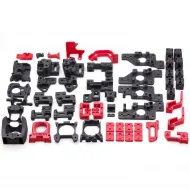
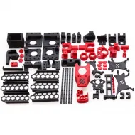
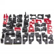
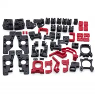
For completing or renewing the structure, see the updated ABS printed parts kit for Voron Trident. Check the selected options and Z-endstop configuration before combining both products.