

- Stock: Out of Stock
- Model: Manta-4MP

Model:

Manta M4P

Manta M8P

Manta M8P V2
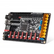
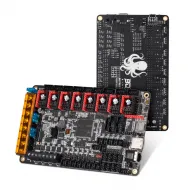
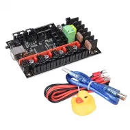
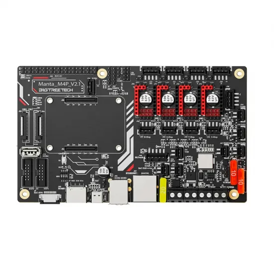
The BIGTREETECH Manta M4P combines a printer controller and a CM4-form-factor computer-module socket on one board. Its four X, Y, Z and E0 driver sockets make it a compact choice for single-extruder machines, Klipper projects and upgrades where fewer connections between host computer and motion electronics are desirable. The host module and drivers are separate components that must be chosen and configured for the machine.
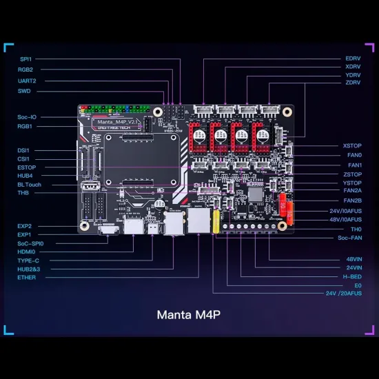
The images and pinout in this listing show the Manta M4P V2.1. Before flashing firmware or following a wiring diagram, check the revision printed on your board and the exact microcontroller fitted to it. Do not infer a revision solely from the name “M4P”.
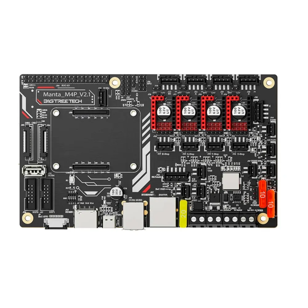
What the Manta M4P provides
- Four driver positions: X, Y, Z and E0. Both Z motor connectors share the same Z driver; they are not two independently controlled Z axes and cannot have separate driver-current settings.
- Replaceable drivers: depending on pinout and jumpers, the sockets support STEP/DIR modules such as A4988/DRV8825 and TMC modules using UART or SPI. The MKS TMC2209 V2.0 is one UART example, provided orientation, voltage, jumper placement and current are checked. Inserting a TMC module does not automatically enable UART, SPI or sensorless homing.
- Power outputs: one heated-bed output and one hotend-heater output. The manual for this board family states limits of 10 A for the bed and 6 A for the hotend, and less than 20 A for the heater, drivers and fans combined. Size wiring, connectors, power supply and protection for the actual loads.
- Fans: FAN0, FAN1 and FAN2 can be jumper-selected for 5 V or the main input voltage (12/24 V), but all three share the selection; different voltages cannot be assigned to each. The separate SoC FAN socket does not use this voltage selection. Verify each fan's rated voltage before connection.
- Sensors and expansion: two 100K NTC temperature inputs, probe/BLTouch, filament-runout, two RGB, EXP1/EXP2, SPI and other auxiliary connections. Configure firmware for the actual thermistor curve; “100K” alone does not identify it.
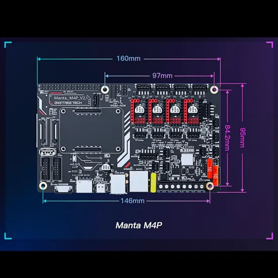
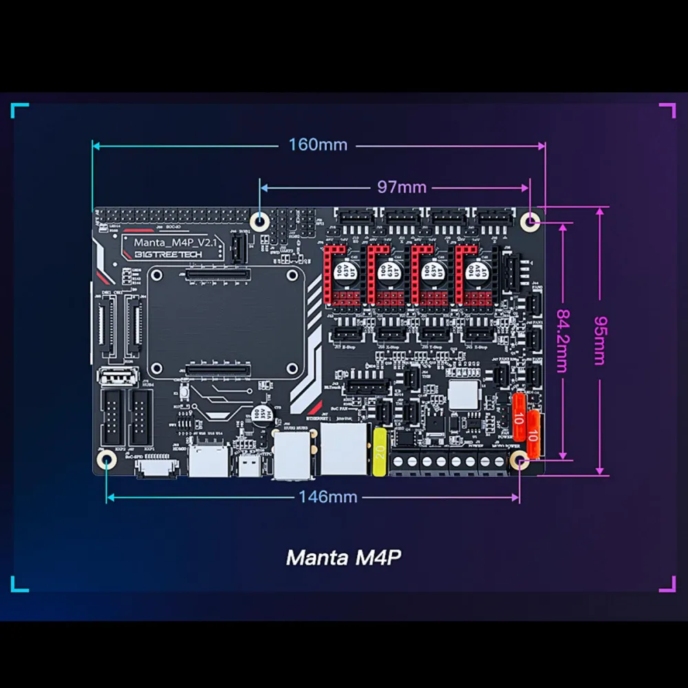
- Dimensions: 160 × 95 mm, with mounting spacings of 146 × 84.2 mm and 97 × 84.2 mm in the drawing. Check clearance for the host module, stepper drivers, heatsinks and wiring.
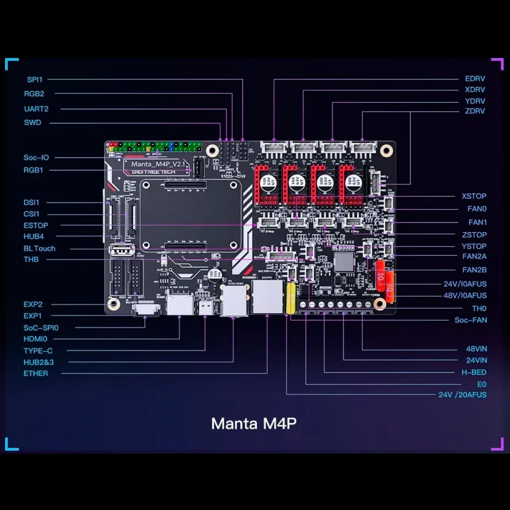
Host module and connectivity
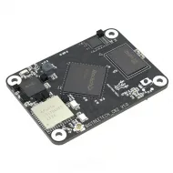
The M4P has a BTB socket for a CM4-form-factor host computer. A Klipper system can use a BIGTREETECH CB2, CB1 or compatible Raspberry Pi CM4, each with the operating-system image intended for that module. CB2 does not use Raspberry Pi OS or a CB1 image. Fit the module with power off, align both connectors without force, and allow for cooling.
The board offers host-facing connections such as Ethernet and USB. HDMI, DSI/CSI and GPIO also depend on the fitted host and its operating-system configuration. Fitting the same socket does not make all peripheral functions or GPIO pin maps identical. The Linux host and the M4P microcontroller need separate setup.
Power and jumpers
The documented M4P main supply is 12 or 24 V DC; onboard conversion supplies 5 V to the host module. A separate MOTOR POWER input can power the stepper drivers independently, with a source-selection jumper for each socket. Do not use a motor voltage different from the main supply without checking every driver's jumper, electrical rating, capacitors and power source. This option does not increase the permitted voltage for the bed, hotend or fans.
With the machine completely powered down, set jumpers for the actual driver mode: STEP/DIR, UART or SPI. Where required, RST and SLP must be bridged; connect DIAG only when sensorless homing is intentionally used and configured. Check terminal polarity, fan voltages and both sensors' room-temperature readings before testing motion or heating.
Firmware: Klipper and Marlin
Klipper: first install the operating-system image appropriate to your CB2, CB1 or CM4 host. For the M4P microcontroller, Klipper's official generic configuration is a starting pin map. Its header specifies STM32G0B1, an 8 KiB bootloader and USB for the board it documents: check the chip marking on your own board before building firmware. After flashing the MCU, obtain its actual path under /dev/serial/by-id/ and adapt printer.cfg to your motors, travel, thermistors, outputs and fans. Example temperatures, PID values and machine dimensions are not universal M4P specifications.
Microcontroller updates through its microSD slot normally use a built binary named firmware.bin; after a successful update it is usually renamed FIRMWARE.CUR. Follow the official M4P firmware guide. This is different from writing the Linux operating system to the host module.
Marlin: the project provides BOARD_BTT_MANTA_M4P_V2_1 for the documented revision. Select a build environment matching the physical microcontroller, configure drivers, temperatures, geometry and wiring for your printer, and verify the pin map before enabling outputs. Marlin does not install or configure the host module's operating system.
Is it right for you?
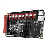
Choose it if you are building a single-extruder printer with four driver channels, want a Linux module on the same board, or are upgrading an older controller as a wiring and firmware project. Choose another board if you need two independently controlled Z drivers, more than one board-controlled extruder, different voltages across FAN0–FAN2, or a drop-in replacement without wiring and firmware changes. For more independent motors, compare the Manta M8P V2.0, while checking your machine's actual requirements.